How to Size a Pneumatic Valve
Compressed air is wildly regarded as the fourth essential utility after electricity, natural gas, and water. That’s why pneumatics is such an integral part of many industries. When it comes to pneumatics, one of the most critical aspects of the system is the valve.
Directional-control air valves, in particular, are those that allow the air to flow in one direction or another. They are used to control the direction of the airflow in a pneumatic system, and getting the sizing wrong can have costly consequences like system malfunctioning.
This article will discuss the basics of properly sizing a pneumatic valve and the different valve options worth considering.
Sizing Basics
You need to consider various factors if you want to correctly size a pneumatic valve. You must understand how this is done to avoid any potential errors that could cause your system to not function correctly.
Determining the size with the flow equation
One of the first things you need to utilize is the flow equation. This factor lets you consider how much flow a valve can deliver to an actuator. The associated rating generally uses the term “coefficient of velocity (Cv).” This Cv (also referred to as valve flow) allows comparison of the flow of different valves. When the value of Cv is high, the flow is also greater.
To match a valve and cylinder, you can utilize the following equation:
Cv = (A × S × a × Cf) ÷ (t × 29)
The variables involved in this formula are the following:
- A = Cylinder Piston Area (π × r2)
- S = Cylinder Stroke
- t = Time (in seconds)
- a = Pressure Drop Constant
- Cf = Compression factor
- (t × 29) = Time (in seconds) it takes for the pressure to drop from start to end pressure
It’s worth noting that the last two variables changes based on the value used from the Sizing Factor table or chart.
Valve sizing chart
If you want to quickly determine the Cv of a valve, you can also utilize a valve sizing chart. This chart generally has various values for Cv, with some of the more common ones being 0.015, 0.030, and 0.060.
The valve sizing chart will tell you the maximum flow of air for each valve size. You can also determine how much pressure is required to open and close the valve.
It’s also worth noting that the valve’s Cv depends on the manufacturer. The sizing chart should have all the information to determine the correct Cv for your needs. Additionally, experts recommend oversizing the valve by about 25% to account for various losses in pneumatic systems.
If you want to get more specific with the sizing, you can also calculate the Cv of each component in the system. This will give you a more accurate picture of how much airflow is required.
Converting Cv to SFCM and ESEOD (Equivalent Square Edge Orifice Diameter)
It’s sometimes helpful to convert the Cv of a valve to two other ratings: Standard cubic feet per minute (SCFM) and equivalent square edge orifice diameter (ESEOD). These ratings can be helpful when you’re trying to determine how much flow a valve can provide.
To convert Cv to SCFM, you can use the following equation:
SCFM = Cv ÷ F
To convert Cv to ESEOD, you can use the following equation:
ESEOD = (Cv × F) ÷ P
The variables involved in these equations are:
- P = Pressure in PSI
- T = Temperature in degrees Fahrenheit.
- F = Factor
Keep in mind that both Pressure (P) and Factor (F) are often taken from a conversation factor table. Let’s say you’re trying to convert your Cv to SCFM.
The Cv value is 0.48 and is being operated at 100 PSI. If you look at a conversation factor table, you’ll notice that 100 PSI equals 0.0177.
Therefore:
SCFM = Cv ÷ F
27 (SCFM) = 0.48 (Cv) ÷ 0.0177 (Factor)
This can also be reversed by multiplying the SCFM with the factor:
SCFM x Factor = Cv
27 (SCFM) x 0.0177 (Factor) = 0.48 (Cv)
Different Valve Options
When you’re looking at pneumatic valves, you’ll notice various types available. The most common ones are the following:
5-port 4-way valve
The 5-port 4-way valve has a separate exhaust port for each cylinder port on the valve. In doing so, flow controls can be added at the exhaust to allow separate control of each cylinder port. This is used most often when controlling a double acting cylinder.
3-position, 5-port 4-way valve
These valves are the same as a 5-port 4-way valve, except that they have three possible center positions. Position one and three are the same as with a 5-port 4-way valve. However, the center position allows three different options for what happens when the valve is de-actuated. The three possible positions are exhaust center, pressure center and blocked center. In the exhaust center position, both cylinder ports will be open to exhaust. In the pressure center position, pressure will be applied to both cylinder ports. Finally, in the blocked center position, all ports are blocked.
This type of valve is also ideal for operations where the cylinder rod needs to move to a specific position and stay there.
5-port vs. 4-port 4-way valves
The main difference between a five ported valve and a four ported valve is that the five ported has a separate port for each cylinder port, while the four ported valve has the two exhaust flows going to the same exhaust port. While the five ported valve allows for easy control of double acting cylinders, four ported tend to be used where this separate control is not required.
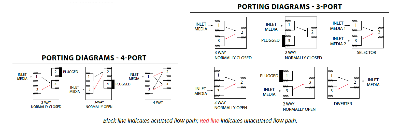
3-way valves vs. 4-way valves
3-way valves differ from 4-way valves in that they only have one cylinder port. In a normally closed application air is ported from the supply port to the cylinder port when the valve is actuated. When the valve is de-actuated the valve opens the cylinder port to exhaust. In a normally open application, the difference is that air is flowing from the supply port to the cylinder port when the valve is not actuated. When actuated, air flow goes from the cylinder port to exhaust port.
4-way valves allow continuous flow from supply to the normally open cylinder port while the normally closed cylinder port flows to exhaust. When the valve is actuated, the flow switches, exhausting the normally open cylinder port and pressurizing the normally closed port.
Most 3-way valves operate single-acting cylinders, while 4-way valves operate double-acting cylinders. Humphrey Balance Valves, 310/410, and 320/420 models are perfect examples of these valves.
Poppet vs. spool valves and their ideal uses
Poppet valves are used in applications where a quick response time is needed. They’re also well-suited for use in high-speed applications. These valves are often used in pneumatic actuators, air tools, and as pilot valves.
On the other hand, Spool valves are better suited for use in low-speed applications. They’re also often used in applications where a high flow rate in a smaller size is needed. These valves are typically used in factory automation applications.
Poppet valves are often direct-acting valves, while spool valves are pilot-operated or remote-pilot valves.
Proportional valves vs. digital valves
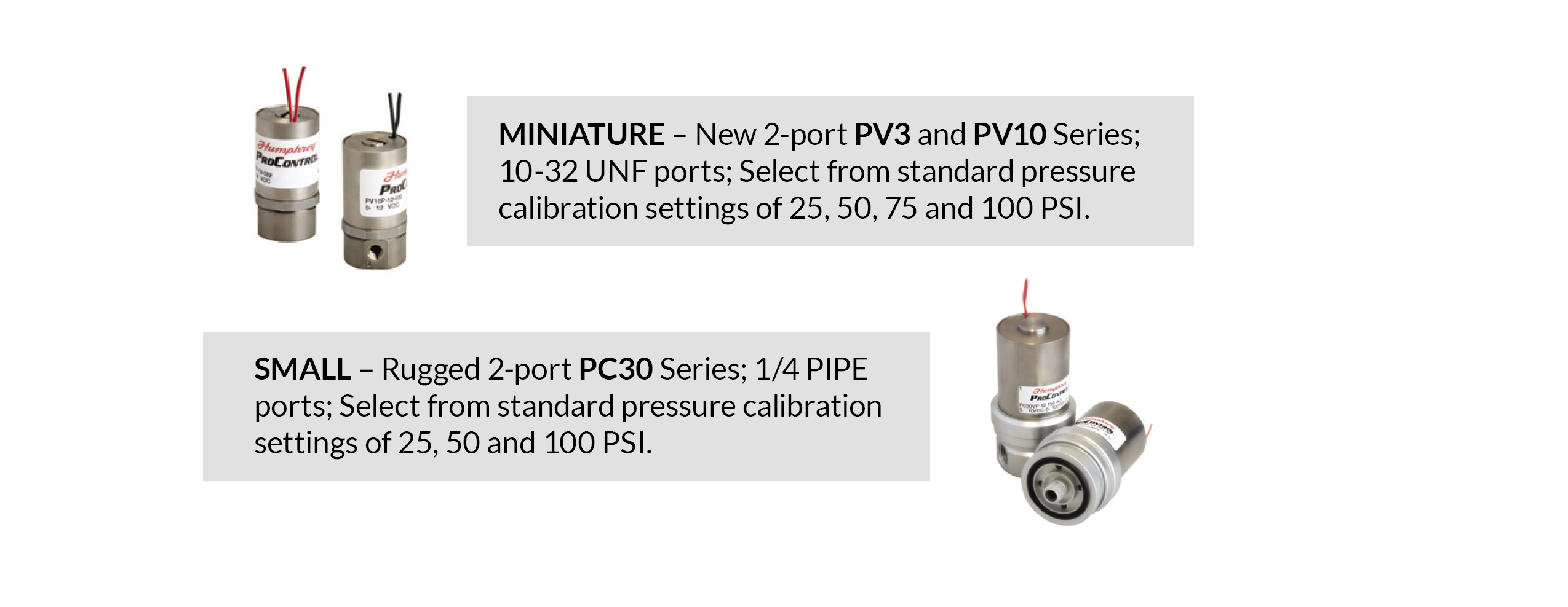
Proportional valves are often used in applications where precise control of airflow is needed. These valves can control the flow of the valve via a variable electrical signal.
Digital valves, on the other hand, have only two states: on and off. These valves can be used to open and close a circuit, start and stop the flow of air, or change airflow direction.
The Humphrey PV3, PV10, and PC30 are well-known proportional valves. For digital valves, the Humphrey Balance Valves are a popular choice.
Liquid Valve
This type of valve is used to control the flow of liquid. It’s often used in applications where precise control of the liquid flow is needed. The most common use for this type of valve is in medical and diagnostic applications. The Humphrey iDP series and HK5 are considered great liquid valve models.
Take Your Time
Today’s article discusses the different types of valves available and their ideal uses. We have also provided information about properly sizing a pneumatic valve using various flow equations and shared the various factors you need to consider.
To ensure safety and efficiency, be sure to take the time to properly size your pneumatic valve and consider following the steps we shared in this guide.
When in doubt, always seek the help of a professional or consult with a trusted manufacturer or distributor.
JHFOSTER is a leading distributor of high-quality actuators, compressors, and pneumatic valves. Contact us today if you have further questions about pneumatic valves or if you’re looking for ways to optimize your systems. Our team of specialists is ready to be of service.